
The gate drive of the UCC2897A (labeled DRV in the schematic) is conditioned and sent to the ISO721M logic input.

The primary MOSFETs (Q4 and Q5) are controlled by the UCC2897A controller.
#DIGITAL ISOLATOR APPLICATION NOTES DRIVER#
The drive signal must be sent to a MOSFET driver IC, which must have minimal propagation delays and adequate current driving capacity.įigure 3 shows the schematic of a 6 V/120 W forward converter in an isolated 48 V input design using a digital isolator. The logic-level output of the isolator is insufficient for directly driving the gates of the synchronous rectifiers. The secondary side logic supply (VCC2) also requires either a 3.3 V or 5 V supply, which can be provided by a low-power linear regulator. The secondary side of the digital isolator also requires extra circuitry to interface with the analog world. D1 allows for a very rapid turn off during the falling edge of the gate drive signal.įigure 2: The logic-level input of the digital isolator requires conditioning

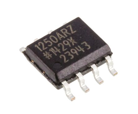
C1 is added to reduce the delay by speeding up the rising edge transition at the isolator input. But, the resistance of R1 and input pin parasitic capacitance results in a significant delay. While the gate drive signal is high, D2 clamps the input to a couple hundred mV above V CC1 and R1 limits the current from the controller gate drive. Translating this signal can be done with a few discrete components, as shown in Figure 2. The gate drive output signals from power-supply controllers are usually 12 V or more. The logic input signal must also be conditioned. Alternatively, a small linear regulator can be used to power the isolator. Digital isolators can draw up to 4 mA from the primary side supply (V CC1 ). Some power supply controllers contain auxiliary reference voltages that may be used however, their current capacity must not be exceeded. The isolators need either a 3.3 V or 5 V supply on the primary side to run the internal logic. As a result, they require extra circuitry to interface with power supply controllers. The maximum delay time of a digital isolator is on the order of 10 ns.ĭigital isolators are designed for digital applications like industrial field bus, computer peripheral interface, servo control interface, and data acquisition. Typically, propagation delays below 100 ns are manageable in switching power supplies. When this happens, the transformer’s secondary windings are basically shorted out by the secondary synchronous rectifiers, resulting in large shoot-through currents and excessive power dissipation. Shoot-through occurs when the primary power switch reverses the polarity of the voltage on the primary of the transformer before the secondary synchronous rectifiers have had a chance to commutate to the off-state. Too much delay can lead to shoot-through currents. Propagation delays are critical when controlling synchronous rectifiers. The maximum data rate of a digital isolator is typically around 150 Mbps, while switching power supplies typically run at frequencies between 100 kHz and 1 MHz. Moreover, digital isolators provide immunity to transients up to 50 kV/μs, which is a necessity in the high dV/dt environment created by switching power supplies. Most isolated power supplies require 1500 V or 3000 V of isolation. The isolation barrier of a typical digital isolator provides galvanic isolation of 4000 V. The performance characteristics of these digital isolators are more than adequate for switching power supply applications. The digital isolator conditions the input signal and differentiates the signal across the isolation barrier through capacitive coupling.įigure 1: The capacitively-coupled digital isolator uses balanced signals to work robustly in high dV/dt environments. It contains a logic input and an output buffer, separated by a silicon dioxide insulation barrier. The emergence of capacitive-coupled digital isolators presents a new solid-state solution to driving synchronous rectifiers.įigure 1 shows a functional drawing of a digital isolator, the ISO721M. Some topologies lend themselves to implementing self-driven synchronous rectifiers, where the gate drive signals are derived directly from the power transformer. While less common, optocouplers are sometimes used.

Gate drive transformers are the most popular method of accomplishing this. The control signals must bridge the isolation boundary with minimal delay. In isolated topologies, the power-supply controller typically is located on the primary side of the isolation barrier, while the synchronous rectifiers are located on the secondary side. Many of today’s switching power supplies implement synchronous rectifiers to improve efficiency.


 0 kommentar(er)
